Tower crane arrangement
Requirement
This project optimizes the layout of tower cranes given a required number of cranes.
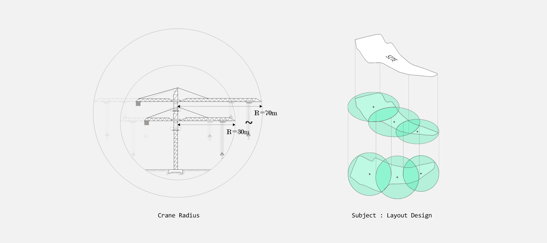
The crane sizes are shown in the diagram below. When arranging three cranes, the questions considered were which crane size to choose and by what criteria each crane should be placed.
 Requirement
From the left, Radius of crane · Project purpose
Designing state space
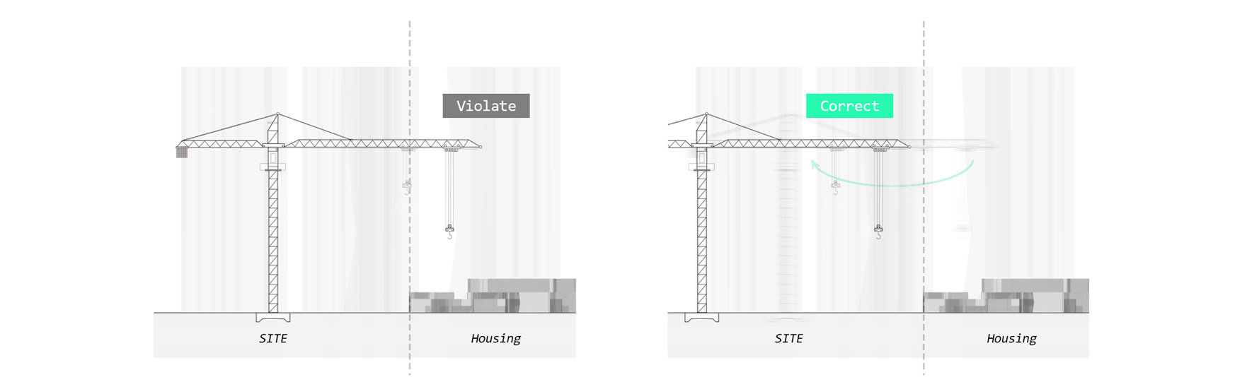
The constraint in this project is to minimize the intrusion of tower cranes into the housing areas around the site.
If a tower crane
invades housing areas, that state space receives a low score.
 Set constraints
A bounding box was created over the given
site, and the positions parameter (the origin of each crane) was generated within it.
A state space reflecting the radius of the selected tower crane is then created based on the origin.
Since it is necessary to check whether the origin of a crane falls outside the given site, a
Point in Polygon algorithm is used to verify this.
Evaluating
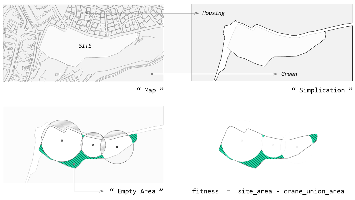
Fitness is defined as the total area of the
given site minus the area occupied by the tower cranes.
Exploring this fitness without any threshold drives the result solely toward increasing the size of the tower cranes.
For this reason, an additional threshold was added to the pre-set constraint by defining an evaluation function.
 Set fitness
More details can be found in the
code.
Three thresholds were set: 1. whether the point is inside the given site, 2. how large the intersected area of the tower crane is, and 3. how much the crane has invaded the housing area.
1. origin_in_region % 2 != 0
2. crane_intersected_area >= 1000
3. housing_intersected_area >= 200
Record & Result
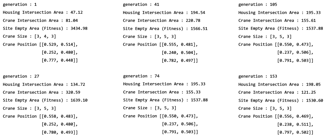
Each generation fitness
Each generation was recorded as follows. After 153 generations, the fitness no longer decreases.
The code and the optimized result within the set constraints are shown below. The areas of the elements used in the fitness evaluation can be examined through the visualized images at the bottom.
Result
From the left, Optimization process · Optimum layout